This article describes the working principle of the stepper motor and the characteristics of the stepper motor controlled by the SCM. The stepper motor is a digitally controlled motor, which converts the pulse signal into angular displacement, that is, to a pulse signal, the stepping motor rotates an angle, so it is very suitable for the single-chip microcomputer control. Stepper motors can be divided into reactive stepper motors, permanent magnet stepper motors, and hybrid stepper motors. The biggest characteristic of the stepping motor, which is different from other control motors, is that it is controlled by inputting a pulse signal, that is, the total rotation angle of the motor is determined by the number of input pulses, and the rotation speed of the motor is determined by the frequency of the pulse signal. It has high-precision positioning, position and speed control, positioning and holding force, action sensitive, open loop control does not have to rely on sensor positioning, high torque at low speed, high reliability, small size, high power and other characteristics, so that it has Wide range of applications. First, the working principle of stepping motor Stepper motor is a commonly used actuator in electromechanical control. Its purpose is to convert electric pulse into angular displacement. Its driving circuit works according to the control signal, and the control signal is generated by the MCU. When the step driver receives a pulse signal, it drives the stepper motor to rotate in a set direction by a fixed angle to control the sequence of the commutation. That is, the power control pulse must separately control the on and off of each phase in a certain sequence. By controlling the number of pulses, the angular displacement can be controlled so as to achieve accurate positioning. Control the stepping motor's steering, that is, the given working mode is positive sequence commutation power. The stepping motor rotates forward. If the power is reversed in reverse order, the motor will reverse. Control the speed of the stepper motor, that is to send a control pulse to the stepper motor, it will go one step, and then send a pulse, it will turn one step, the shorter the interval between the two pulses, the faster the stepper motor will turn. At the same time, the speed and acceleration of the motor rotation are controlled by controlling the pulse frequency so as to achieve the purpose of speed regulation. Second, the design plan This design uses 51 single-chip AT89C51 (crystal frequency of 12MHZ) on four-phase six-wire stepper motor (internal resistance of 33 ohms, step 1.8 degrees, rated voltage 12V) to control. The square wave with timing output from the I/O port is used as the control signal of the stepper motor, and the signal drives the stepper motor through the chip ULN2003. ULN2003 is a high pressure, high current Darlington display consisting of seven silicon NPN Darlington tubes. Each pair of Darlington of ULN2003 is connected in series with a 2.7K base resistor. It can directly connect with TTL and CMOS circuits at a working voltage of 5V, and can directly process data that originally required a standard logic buffer. ULN2003 has a high operating voltage, high operating current, sink current up to 500mA, and can withstand 50V in off-state, and the output can also run in parallel with high load current. Through the ULN2003 constitute a stepper motor driver circuit, the circuit diagram shown in Figure 1. The 25-28 ports of 51 are connected to the 1-4 inputs of ULN2003. In addition, use the keyboard to control the status of the motor, and use the digital tube to display the motor speed, using 74LS164 as a 2-bit single digital display driver. 74LS164 with latches, using serial connection can save I/O port resources. Its circuit diagram is shown in Figure 2. Send data to CLK and DATA through the 51 TXD and RXD ports. Figure 1 51 microcontroller control stepper motor circuit diagram Figure 2 shows the circuit diagram Third, the expected goal Connect Fig. 1 to Fig. 2 to make it realize: press the start button, the motor rotates, press the plus 1 button, the speed increases, press the minus 1 button, the speed decreases, the maximum speed is 100 rpm, the minimum speed is 25 Turn / minute, press the stop button, the motor stops. The speed value is displayed on the digital tube. Based on the above selected options, the overall process is shown in Figure 3. Figure 3 system circuit flow chart Conclusion Stepper motors designed to achieve the basic goals, after debugging and modification, but there are still problems, such as pressing the switch when there will be instability, the speed is sometimes chaotic, sometimes there are some unsatisfactory display, the work behind is in the software Modify the hardware and other aspects to fully achieve the desired goals.
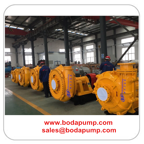
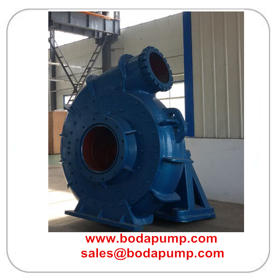
Gravel Dredger Pump includes dredge Slurry Pump,gravel pump, sludge dredge mining pump, dredge gravel slurry pump, gravel sand pump, dredging pump, dredge pump sand mining pump, river sand suction dredge pump, discharge pump for pipe jacking. Gravel Pump is a single stage, single suction, cantilever,horizontal structure ,The dredging pump structure is divided into two kinds of structure according to the size of pressure discharging, ie single and double pump casing;According to the driving type ,it can be divided into two kinds of typical structures, one type is with self-bracket,another one type is with pump and gearbox together (i.e.,gear box ,motor as a whole) self-bracket type lubrication type has two types of lubrication ,grease or oil lubrication .
Gravel Dredger Pump Gravel Dredge Pump,High Capacity Dredge Pump,Portable Dredge Pump,Gravel Pump,
Sludge Dredge Mining Pump,Gravel Sand Pump,Dredging Pump,Dredge Pump Sand Mining Pump,River Sand Suction Dredge Pump Shijiazhuang Boda Industrial Pump Co., Ltd. , https://www.mineralslurrypump.com


Application: This pump is used for dredging in river, mining in deep-sea, desilting in reservoir and reclamation by pump filling along the coast.
WN series dredge pump is my company developed a large of mud pump. Light weight, wear resistance, superior performance dredging and so on.
Function Introduction:
1. This pump is of horizontal cantilevered single-casing centrifugal pump.
2. Construction of this pump is of single casing connected by means of clamp bands and the discharge direction of pump can be oriented in any direction of 360. the type of pump possesses the advantages of easy installation.
3. The cylinder –type bearing assembly with oil lubrication is adopted by the pump. It is suit for adjusting the distance between impeller and pump. The bearing assembly uses oil lubrication.
4. Three kinds of shaft seal---mechanical seal, expeller seal and packing seal
5. Wide passage , good performance of NPSH, anti-wearing and anti-corrosion, and high efficiency,
6. The type of driver just have v belt driver, gearbox driver, elastic coupling driver, fluid couplings driver, frequency conversion driver, silicon controlled rectifier speed regulation etc.
Our dredging pumps are widely used to dredge and dam in the rivers, ports and wharf over our country, such as Yangtze river , The Yellow River , Liao River, and Zhujiang Delta. Besides, sold to Europe, Middle East and Southeast Asia. CCS (China Classification Society) has inspected each set.


Microcontroller's Control of Stepper Motor
