In this paper, combined with the actual control experience and the latest development trend and technology of many large-scale blast furnace flow control valves in China, the flow control valve driven by a hydraulic proportional valve is introduced first, and the control strategy, strategy and experience are introduced. Then, a hydraulic servo valve is introduced. The new material flow control valve system, which has the characteristics of good dynamic response, high control accuracy, and good stability, has been successfully applied on a large-scale blast furnace in China, and has initially solved this problem in blast furnace control.
â— Filter media is Complex Fiber, Resin-Impregnated Paper, Stainless Steel Sintered Metal Mesh, control cleanliness effective.
â— First bubble point per ISO2942.
â— Flow resistance per ISO3968.
â— Retained capacity and Filter efficiency per ISO16889.
â— Mass filtration precision for choose.
â— The size can make to order according to the customer's demand.
Gylw Series High Pressure Line Filter Filter Element Types,Ryl620 High Temperature Filter Element,Ryl650 High Temperature Filter Element,High Temperature Filter Element XINXIANG PINGYUAN AVIATION HYDRAULIC EQUIPMENTS CO.,LTD , https://www.coupling.pl
1 proportional valve based flow control valve control system
    At present, large and medium-sized blast furnaces in China are mostly equipped with flow control valves and drive devices provided by PW Corporation. The flow control valve is driven by a hydraulic proportional valve. High-speed / low-speed and stop signals are used for flow control valves. Speed ​​control. It is the unreasonable configuration of the PW company that makes it difficult to achieve reliable control of the flow control valve in practical engineering applications. In order to solve this problem, we have repeatedly studied and experimented in engineering practice, and summed up a feedforward and adaptive control method, basically solved the control and reliability problems of the flow valve driven by a proportional valve. .
1.1 flow control valve movement process analysis
    The fundamental need for flow control valve control is to ensure the accuracy and reliability of its position control while ensuring its high-speed operation. In order to explain the control principles and methods of the flow control valve, it is necessary for us to first control the flow control valve. Exercise and stop the process for analysis.
    Figure 1 shows the speed dynamic response curve of the blast furnace top flow control valve provided by PW . 
Figure 1 PW flow control valve speed characteristic curve
    From Figure 1, we can see that, in an ideal situation, to accurately stop the flow regulating valve at high speed, the following steps need to be taken:
    ( 1 ) At a predetermined deceleration angle δj, the flow control valve is changed from high speed to low speed. It can be seen from Fig. 1 that after the command is issued for about 0.3s , the flow rate of the flow control valve drops from 15 ( ° ) /s to 5 ( ° ) /s , during which the opening of the valve movement ( valve reduction inertia angle δhtj ) is approximately ( 15 - 5 ) / 2 × 0.3 = 1.5° .       Â
    ( 2 ) After a period of steady-state speed (approximately 0.1 s on the response curve ), the valve speed is stable at 5 ( ° ) /s . During this period, the flow control valve operating angle (valve mechanical parking angle δltj ) is approximately 0.5° .
    ( 3 ) After the speed is stable, the stop command is given when the parking angle is δt (the speed reference value becomes 0 ( ° ) /s ), the valve stops after about 0.2s , and the flow control valve operates during this period of time. The angle is approximately ( 5/2 ) × 0.2 = 0.5° .
    It can be seen from this that it is important to ensure that the material flow control valve is properly stopped and that the appropriate deceleration angle δj and parking angle δt are determined .
1.2 Feedforward control
    The so-called feedforward control of the flow control valve stopping process is to introduce a suitable deceleration angle δj and stop angle δt in the stop control process, and through the control of these two angles, the accurate control of the flow control valve opening degree is achieved. purpose.
    Because each blast furnace flow control valve system and hydraulic system characteristics, blast furnace control system and communication methods are not the same, the deceleration angle δj and stop angle δt of the material flow control valve are also different. In the actual engineering design, a value can be calculated based on the characteristic curve of the material flow control valve provided by the manufacturer, the scanning speed of the blast furnace control system, and the communication speed of the angle detection system, and then the angle can be corrected through field experiments in field debugging.
Δj can usually be found by equation ( 1 ):
        ( 1 )
    In the formula, δhtf is the additional deceleration angle of the material flow control valve, considering various delay factors, δhtf≈ ( 2TS +Tti ) V1 , where TS is the controller scan time, ms , Tti is the encoder interface delay time, Ms , V1 is the initial velocity of the low-speed movement of the valve, ( ° ) /s ; δhsw is the deceleration and stabilization angle, and the engineering needs to be adjusted according to the actual situation on the site, usually adjusted to about 3° . The most rapid increase in the deceleration angle needs to be determined based on the actual adjustment based on the above calculation angle.
Δt can usually be found by ( 2 ):     Â
        ( 2 )
    In the formula, δm is the stopping angle set for this time; δltf is the additional parking angle of the flow regulating valve, considering various delay factors. In actual debugging, after considering various comprehensive factors, generally take δltj+δltf at about 3° .
    After adopting the feedforward control method, the material flow control valve can basically guarantee the control accuracy of about 0.1° when the mechanical and hydraulic systems work normally and the working state is stable . However, after the blast furnace is put into operation, the mechanical and hydraulic system characteristics of the valve will change with time, and this change will cause corresponding errors in the control.
1.3 adaptive piecewise linear interpolation control [ 1 ]
    To solve the problem of changing the mechanical properties affect control accuracy, we feedforward control based on the previous added control algorithm is called a "piecewise linear interpolation Adaptive Control",. The control concept includes two kinds of control methods. First, the flow control valve system adopting the feedforward control method is regarded as a black box. A corresponding control model is established based on the relationship between the black box input / output; then the control model is Based on the above, adaptive control is used to dynamically correct the control error due to factors such as mechanical characteristics change.
1.3.1 Stage interpolation method
    In engineering practice, we often encounter such a situation: For a control object, there is a certain function y=f ( x ) between its various control parameters , although we know that it must be solved within a certain range. , but it is difficult or impossible to find the function of its determination, only through the on-site experiment to obtain the list of correspondence between xi and yi .
    For the above problems, a variety of methods can be used to find solutions to the corresponding function relationships. The simpler and more practical method is the " phasewise interpolation method . " Segmented interpolation uses a simple, well-known function p ( x ) to approximately express an unknown table function f ( x ) within a certain range , by solving a known approximate function p ( x ). The solution of the unknown function f ( x ) can be approximated . The alternative function p ( x ) can be thought of as the first-order linear function as follows
        ( 3 )
    When the function f ( x ) is replaced by a linear function ( 3 ) , as long as any two points ( xn , yn ) of the table function f ( x ) are known , ( xn+1 , yn+1 ) can be approximated by the following interpolation formula. Find any point value between ( xn , yn ), ( xn+1 , yn+1 ).
        ( 4 )
    Thus, the more the corresponding points ( xn , yn ) of the table function f ( x ), the higher the accuracy of the approximation y obtained by Equation ( 4 ) .
1.3.2 The realization of control
    The establishment of the flow control valve control model is to find out the relationship between the flow valve setting opening αs and the actual opening αa . For this purpose , a list function between the set opening degree αs and the actual opening degree αa is measured in the effective control angle of the material flow control valve (usually 0 to 60° ) , and then the list function is fitted to The function αs = f ( αa ) to obtain the flow control valve control model.
    According to the actual opening degree αa required by the flow regulating valve , αs is found in the model list function . If there is no point that matches the actual opening degree, two points αa and αa adjacent to αa can be found first , and then the opening degree can be determined. Αs and use it as the opening setting to control the flow control valve.
    In order to correct the control error, the control program records the preset opening degree αs and the actual opening degree αa of the material flow control valve , and obtains the relationship data of ( αs , αa ). Compare αs and αa , if the difference is greater than the set control error (for example, 0.2° ) and the control model data is allowed to be modified, the control program will use αa instead of the corresponding value in the original model list function to complete the flow control valve opening. Degree of precision control " adaptive control " process.
    The actual application on the site shows that: After adopting the adaptive control method based on the feedforward control, the flow control valve can usually achieve satisfactory results. The control accuracy is generally about 0.1° , which basically ensures the flow control valve. The long-term stable work.
2 defects flow regulating valve control system based on the proportions of the valve
    ( 1 ) Poor stability of the control system
The " adaptively controlled piecewise linear interpolation method " works well and can work reliably and stably under normal conditions, but when the system is unstable and there is no regular change, for example, when the system pressure is irregularly changed due to a hydraulic system failure, Make it difficult to work properly.
    ( 2 ) It is difficult to meet the need for dynamic adjustment
    It is experimentally proved [ 2 ] that in the blast furnace fabric process, corresponding to a constant opening angle [ alpha] , the material flow rate Q of the fabric is not constant. The relationship between Q and the material mass P , the particle size D of the material , the specific gravity Ï , the material quantity W in the tank, etc. can be approximated by formula ( 5 ):
        ( 5 )
    In the formula, the current fabric P , D , Ï certain, only W change in the process of fabric, in the fabric process to ensure a constant Q will change α . The Q curve is roughly as shown in Figure 2 [ 2 ]. 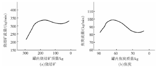
Figure 2 The relationship between the remaining amount of material in the tank and the material flow rate
    To ensure that Q does not change, it is necessary to adjust α according to the curve of the curve in Figure 2. The study shows that the adjustment angle is generally around ±2° . The traditional proportional valve has poor dynamic response. Even at low speeds of 5 ( ° ) /s , dynamic adjustment of ±2° is very difficult.
    ( 3 ) High requirements for control system
    The flow control valve has two operating speeds, high and low. At high speeds, the operating speed is not less than 15 ( ° ) /s , and at low speeds is 5 ( ° ) /s . If we assume that the update speed of the control system I/O interface board is fast enough and ignore the delay of encoder data transmission through the bus, etc., when the control accuracy needs to resolve an angle of no more than ±0.2° , the scan cycle should be:
    TS≤ ( 0.2/15 ) × 1000=13 ( ms ) at high speed
    TS≤ ( 0.2/5 ) ×1000=40 ( ms ) at low speed
    It can be seen that in order to ensure that the control system can distinguish the control accuracy of ±0.2° , the minimum required system CPU scan cycle is no more than 40ms . If other factors are taken into consideration, the cycle time should generally not exceed 20ms . This puts forward certain configuration requirements for the blast furnace control system. When using different control systems, due to different system performance, the control effect of the flow control valve will have a certain impact.
    In order to overcome these shortcomings, China Metallurgy CCID Engineering Technology Co., Ltd. has developed a flow control valve control system based on hydraulic servo valve control.
3 Flow control valve control system based on servo valve
3.1 Servo valve characteristics
    Hydraulic servo valve has high dynamic response speed and high control precision. It has been widely used in the occasions where high precision and rapid response are required in the rolling control of the rolling mill. Figure 3 shows the response curves of the servo valve and proportional valve. 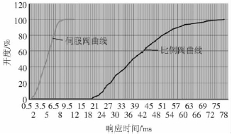
Figure 3 Servo valve and proportional valve response curve
    Through analysis, the following conclusions can be drawn:
    ( 1 ) The response delay time of the proportional valve to the step signal is approximately 20ms , and the servo valve is approximately 0.5ms . Therefore, the sensitivity of the servo valve to the input signal is approximately 40 times that of the proportional valve .
    ( 2 ) The response of the proportional valve to the step signal is about 80ms from 0 to 100% , and the servo valve takes about 9ms , so the servo valve adjustment speed is about 9 times that of the proportional valve ;
    ( 3 ) The servo valve dynamic response speed is approximately 7 times that of the proportional valve .
    From the above conclusions, the servo valve is more advantageous than the proportional valve in the dead zone, dynamic response and rapid adjustment.
3.2 Hardware Composition
    We use the blast furnace master PLC to control the flow control valve system. The system block diagram is shown in Figure 4. In the figure, 1 is the PLC controller body, and the CPU of the PLC is required to use a 32b processor with a floating-point arithmetic unit. scanning period is not greater than 20ms, to ensure fast and accurate control of the servo valve; 2 is a power interface controller, comprising an input power connector and an external controller for the external power supply interface device and the external valve amplifier board encoder; 3 PLC output speed control command and servo valve spool displacement feedback analog signal interface (this analog interface uses high-speed module); 4 is the flow control valve position detection encoder 7 and 8 and PLC communication between the high-speed network Interface; 6 is the flow control valve driven by the hydraulic servo valve, which can control the speed of the valve
â— Used in hydraulic system.
Regulating valve control method and improvement