The dryland area in China accounts for 52.5% of the total arable land. How to resist drought is a major scientific and technological issue in the dryland agricultural production and ecological environment improvement in China. In the science and technology projects in the fields of agriculture and resources and environment, the water transport in the soil-vegetation-atmosphere interface, the water physiology and ecology of plants and vegetation communities, the relationship between vegetation restoration and arid environment have always been the core issues of scientific research, and the natural environment The complexity and irreproachability of the study have limited the quantification and progress of research work. On the basis of making full use of natural resources, the artificial climate room has comprehensively applied related disciplines such as biological sciences, information sciences, and automatic control sciences. Various environmental factors in the environment, such as temperature, humidity, light, and CO2 concentration, are controlled and adjusted to meet scientific research requirements for specific environments.
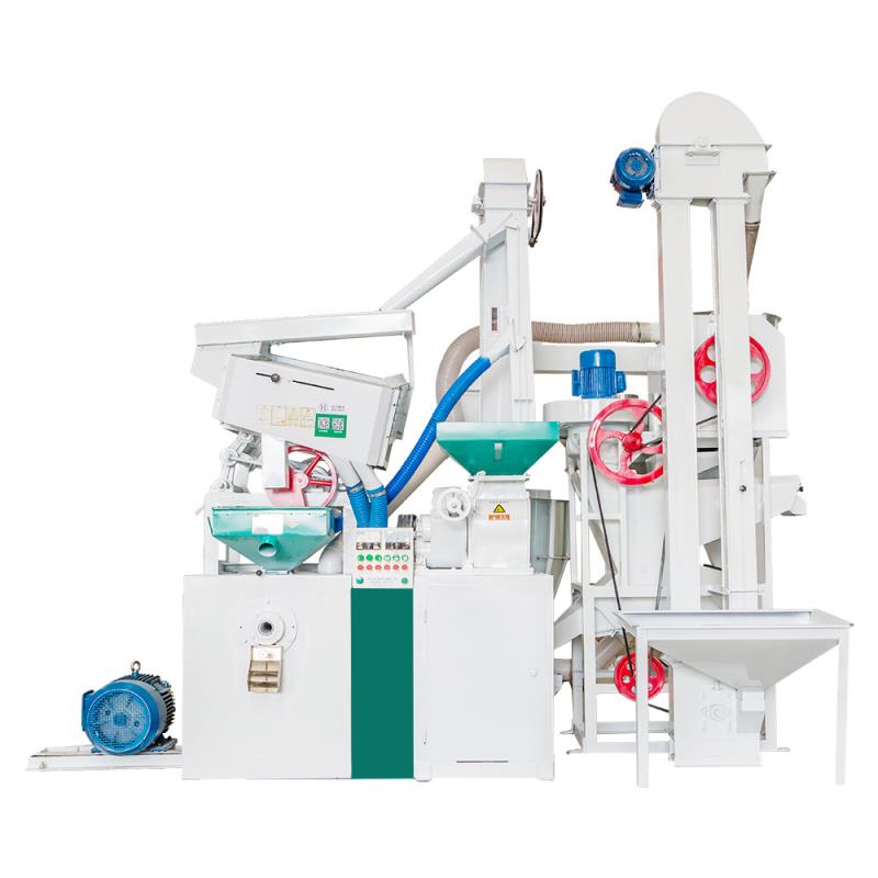
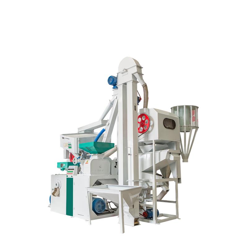
Rice Hulling Combination Rice Machine
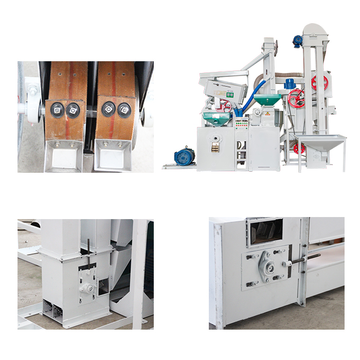
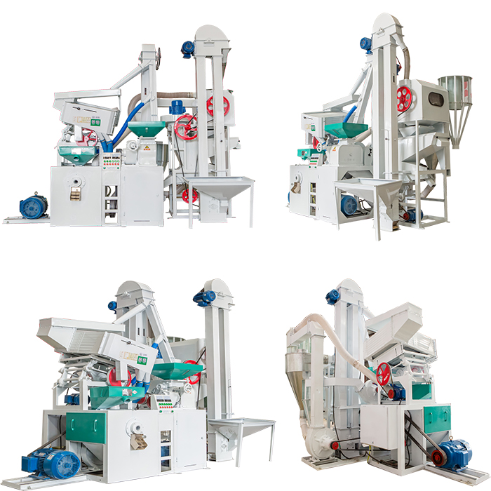
The combined rice husker has the advantages of low power, low energy consumption, large output, easy operation and good maintenance. The machine consists of a single-link elevator, a multifunctional cleaning and stone removing machine, a new split rice huller ( the core part of the equipment ), a double-link elevator, a grain rough separating screen, a negative pressure rice refining machine, a broken rice separating screen, a multifunctional crusher and a central centralized controller. The fuselage is made of wear-resistant glass pipes, which are durable and beautiful.
Equipment parameter:
Main characteristics of rice milling machine:
1. compact construction, beautiful appearance.
2. less broken rice increment.
3. easy to operate.
4. steady performance.
5. national patents.
MLNS 20/15 Rice Mill Machine,Automatic Rice Mill Machine,Small Combined Rice Mill Machine,High Efficiency Rice Mill Machine Sichuan Doujin Technology Co., Ltd. , http://www.doujinmachine.com
Based on the physical prototype of the research project of the large-scale instrument and equipment development program of the Chinese Academy of Sciences, the Artificial Dry Climate Climate Room, this paper summarizes the characteristics of the scientific research-type artificial arid-environment climate chamber and simulates and controls four environmental factors of temperature, humidity, light, and CO2 concentration. The technical solution. The program control of parameters such as temperature, humidity, light, and CO2 concentration is achieved to meet the requirements of constant or gradual change, ie, the temperature and humidity change process is continuous and does not produce step-like changes; the light source is arranged in accordance with the growth and development of the plant, and the light source spectrum line Similar to the solar spectral lines, the illuminance is even and can be grouped and set automatically according to the set light intensity. The minimum adjustable time unit is 1 minute, and a 24-hour cycle is performed; there are new air and exhaust systems, and the air distribution, heating, and cooling methods are reasonable. , Energy-saving effect is good; with a network of hierarchical management and remote management capabilities, and has a mobile phone wireless signal supply equipment alarm operation abnormal function. The climate room can provide an ideal research environment for scientific research work such as agricultural development in the drylands and ecological environment construction.
1 Design of Technical Indicators for Artificial Dry Climate Climate Room 1.1 Selection of Technical Indicators According to the development goals of the Artificial Arid Climate Climate Room, the four main climate factors, lighting, temperature, humidity, and CO2 concentration required for plant growth and development are selected for simulation and control. The main object, and use for scientific research. Therefore, each controlled climate element is not necessarily an ideal plant growth and development environment, but more emphasis on creating various extreme climate conditions for plant growth and development, such as low temperature, low humidity, long days, high light intensity. According to the statistical data of climate data, these features of the climate and environment are ubiquitous in the northwest region of China, and thus have become a practical need for the design of climate chamber technical indicators. On the other hand, the climate chamber has higher requirements than the conventional climate chambers in the three indicators of the lower limit of relative humidity, the upper limit of illumination intensity, and the lower limit of temperature. According to research and literature reports, the temperature range of common climate chambers is 10 to 40°C, relative humidity is in the range of 50% to 90%, and the photon flux density is in the range of 200 to 800 μmol/m2·s, which is the temperature range designed by this climate chamber. It is -10 to 40°C, the lower limit of relative humidity is 30% to 90%, and the photon flux density is 200 to 1200 μmol/m2·s. This technical indicator offers the possibility to simulate drought, low temperature, high light and strong climate. As the range of change of controlled elements increases, the difficulty of control also increases. For example, due to the increase of the light intensity, the radiant heat that comes out of the light source increases, which makes temperature adjustment more difficult. The technical indicators of the climate chamber are shown in Table 1.
Table 1 Artificial Climate Climate Room Specifications 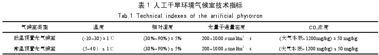
1.2 Climate Room Layout and Construction Process The Climate Room is located at the Institute of Soil and Water Conservation at the Northwest A&F University and consists of 2 floors. The first floor is an artificial intelligence climate chamber that can accurately control temperature, humidity, light, and CO2 concentration. The second floor is at a certain temperature and humidity. The general greenhouse that can be controlled within the scope, this time focuses on the artificial intelligence climate chamber.
The artificial intelligence climate room is divided into six control units, each of which can simulate four environmental factors of temperature, humidity, light and CO2 concentration. In order to reduce the fluctuation of environmental factors caused by opening and closing during the experiment, a buffer room was designed outside the climate. The buffer room is equipped with CO2 gas source cylinders and decompression equipment, and is equipped with facilities such as pools and test benches. The climate room on-site control box is concealed in the wall. Each unit in the climate chamber is equipped with a high-density polyurethane color steel plate integrated cabinet in the building frame. The geometry of the cabinet is: 4.0m × 2.5m × 2.0m, and the effective volume is 20m3. The cabinet technology is designed and manufactured in accordance with the national "GMP" standard, making the climate chamber fireproof, waterproof, heat-insulating, heat-insulating, sound-insulating, non-toxic, odorless, and antistatic. An equipment layer is designed on the top of the cabinet, and all the heating, cooling, humidification, ventilation, light and CO2 distribution pipelines are installed on the equipment layer.
2 Regulation of various factors in artificial climate climate chambers 2.1 Temperature control The temperature control is borne by two systems, one is an air conditioning system and the other is an airflow organization system. The air-conditioning system provides the heat source and the cooling source for temperature rise and fall. The airflow organization system transfers the heat source or the cold source to the climate chamber in a reasonable manner, thereby providing a set temperature environment.
2.1.1 Analysis of Air Conditioning Load Characteristics Climate chamber temperature changes come from two sources.
(1) Annual and daily changes in temperature. As an artificial environment climate chamber must overcome this change and establish artificially controllable temperature range and change process. However, this objective existence is the establishment of the artificially controllable temperature range and background conditions of the change process. It is a factor that must be taken into account when designing the air-conditioning system.
(2) Radiant heat generated by artificial light sources. In order to meet the light conditions of plant growth and development, the climate room has designed an overhead light source with light and effective radiation of 200 to 1000 μmol/m2·s. The light source has an electric power of 16.8 kW. The light-to-electric conversion efficiency of an artificial light source is about 35%, and a large amount of heat enters the climate chamber in the form of radiant heat and convection heat.
The radiant heat is absorbed and stored by the floor, walls, laboratory equipment and experimental materials in the climate chamber, and then slowly released. This absorption-storage-release process of radiant heat forms the lagging heat load of the air conditioning system in the climate chamber. Convective heat is the instantaneous heat load of the air conditioning system as it enters the climate chamber.
2.1.2 The design of the air-conditioning system can be seen from the analysis of climate chamber heat load and the development goals of the climate chamber: Large changes in heat load, poor thermal inertia, and high precision control are problems that must be addressed in climate chamber air conditioning systems. Through experiments and comparisons, the air-conditioning system program adopts a variable-capacity cooling intelligent technology program, the core of which is the use of dual units and digital cooling capacity adjustment technology in each climate chamber. That is, according to the size of the heat load, the number of unit operations is automatically switched. At the same time, in the refrigeration cycle, the refrigeration compressor is subjected to cooling coal control. That is, the control system collects the temperature in the climate chamber and compares it with the set temperature according to the required cooling capacity or heating amount in the room, and controls the computer through a PID (Proportion Integration Differentiation) control and a fuzzy control algorithm. Automatically control the number of compressors and the amount of cold coal in the compressor to precisely control the energy of the input climate chamber, so that the input energy of the climate chamber is balanced with the energy dissipated by the air chamber, and the “shock†is reduced, so as to achieve precise control and temperature The purpose of smoothing changes and saving energy. Through actual evaluation, intelligent control units can reduce power consumption by 40% compared to ordinary control units. The comparison of the temperature control volatility between the intelligent control unit and the ordinary unit and the comparison of the heating rate are shown in Fig. 1, and the measured energy consumption comparison is shown in Fig. 2.
Fig.1 Comparison of temperature control fluctuation of intelligent control unit and ordinary unit 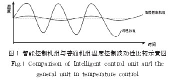
Figure 2 Comparison of energy consumption between intelligent control units and ordinary units 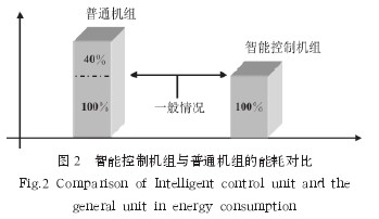
2.1.3 Design of air flow organization Each climatic room consists of a single box and is placed in a larger building space. The indoor unit of the climate room air conditioning system is installed in the equipment layer and passes through the air ducts and climate. Chambers are connected. Air circulation uses a side-by-side circulation method. The airflow is blown horizontally from the diffuser grilles on one side of the climate chamber, and is diffused from the climate chamber to return from the return grille on the other side of the climate chamber, forming a horizontal single-item airflow in the climate chamber, so that the airflow is evenly distributed and the temperature is The field is reasonable. The climate room adopts an overhead light source light box structure, and a lamp air cooling system is designed in the light box to radiate the radiation generated by the light source out of the climate to reduce the load on the air conditioning system. The airflow organization diagram is shown in Figure 3.
Figure 3 Air flow organization 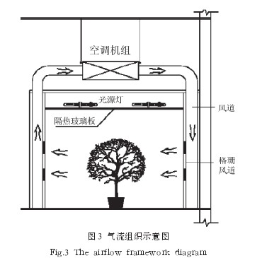
2.2 Two principles for designing light sources for artificial climate chambers: First, the spectrum of the light source is analogous to the spectrum of sunlight; second, the light intensity of the light source is greater than the light saturation point required for the growth and development of the cultivated plants.
Fig. 4 Composition of each band of the spectrum of sodium lamps and metal halide lamps 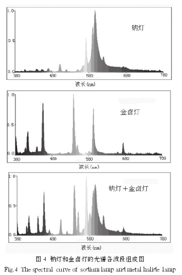
Studies have shown that the spectral lines required for photosynthesis of plants do not include all solar spectral lines. The required spectral lines are mainly distributed in the 400-500 nm violet region and the 600-700 nm red region, and the other spectral lines of the photosynthetic plants. Contribution does not contribute much. Comprehensive comparison of the spectral curves of various plant-type artificial light sources at home and abroad, the Philips agro-sodium lamps and metal halide lamps in the Netherlands were selected, and the spectrum performance obtained by the combination of sodium lamps and metal halide lamps satisfies the requirements for photosynthesis of plants in light. The spectral composition of each band is shown in Figure 4. Assuming a maximum spectral intensity of 1, the spectral intensity of the other bands is the relative proportion of the maximum spectral intensity.
In order to provide a light environment with different light intensities, all sodium lamps and metal halide light sources are divided into high, medium, and low grades, and are alternately arranged in combination to provide a balanced light environment for plant growth and development.
2.3 Control of humidity The control of humidity is divided into two subsystems with opposite functions of humidification and dehumidification.
2.3.1 Humidification Subsystem The climate chamber uses a stainless steel electric heated humidifier. Its working principle is that the electric heating tube is submerged in water, and when the electric heating tube is energized, the electric heating tube generates heat, thereby turning the water into water vapor. The humidifier has a constant temperature and preheating system to ensure that the required amount of humidification is quickly achieved. The electric heating pipe adopts low power and high density design and adopts special scale inhibition technology. It is suitable for all kinds of water quality and greatly prolongs the life of the electric heating pipe. In order to ensure the reliability of the humidification process, humidifier-specific water supply and drain lines are installed in the climate chamber. The humidity control process is:
The humidity sensor collects the humidity parameters of the climate chamber and compares the humidity parameters set by the computer with the experimental ones. The PID and the fuzzy control algorithm are used to control the working state of the humidifier so as to precisely control the humidity of the climate chamber.
2.3.2 Dehumidification subsystem The on-site execution components of the dehumidification function are the air-conditioning refrigeration unit and the electric heater. The control process is the same as the humidification subsystem.
2.4 Control of CO2 CO2 regulation is precisely the CO2 compensation control, because in the climate chamber technical indicators, CO2 changes from the atmospheric background to 1200 mg/kg. The CO2 control system uses an infrared CO2 sensor manufactured by KCD Corporation of Korea to measure the CO2 concentration in the climate chamber. The CO2 gas source is stored in liquid cylinders. After the decompressed CO2 gas passes through a dedicated pipeline to the climate chamber, CO2 gas nozzles and solenoid valves are installed in the pipeline. The control process is: the infrared CO2 sensor measures the CO2 concentration in the climate chamber, and compares the CO2 concentration set by the computer with the experiment, and accurately controls the CO2 concentration in the climate chamber through the PID and the fuzzy control algorithm. If the CO2 concentration in the climatic chamber is higher than the atmospheric background and needs to be reduced, absorption through the fresh air ventilation system or plant growth decreases.
3 Automatic Control System of Artificial Drought Environment Climate Room Automatic control system adopts modern advanced theories and technologies such as intelligent sensing technology, fuzzy control technology and network communication technology, combined with the need for precise control of temperature, humidity, light and CO2 in this climate chamber. , set up a hardware environment and developed an automatic control system. Due to space limitations, only its physical structure and technical characteristics are introduced.
3.1 Physical Structure of Automatic Control System The control system consists of two physical structures. The first floor is equipped with an independent computer control unit with a liquid crystal touch screen for each climate chamber, including a control computer, a color high-brightness TFT liquid crystal touch screen, a temperature and humidity sensor and its communication, a device drive circuit, and control software. Climate room single control of all parameters and equipment (ie manual mode). The second layer consists of industrial control computers and communication networks, and assumes the optimal control calculations and measurement data management of each control element of the system (ie, automatic mode). The two layers are connected via an industrial fieldbus. The hardware structure of the automatic control system is shown in Figure 5.
Figure 5: Automatic control system hardware block diagram 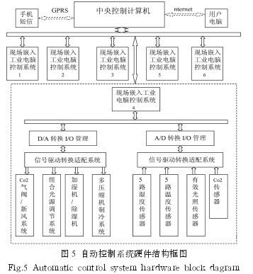
3.2 Technical features of the automatic control system (1) The two-layer structure of the physical topology improves the reliability of the system operation. The first level can work independently from the second level. At the same time, a distributed structure is used between each independent computer control unit on the first floor and the upper computer. This can avoid the damage of one control unit and affect the normal operation of other units, and can not only control the climate room through the upper computer. The climate chamber unit can also be operated directly by the on-site control unit. This two-layer physical structure ensures the reliability of the climate chamber operation.
(2) The software has advanced algorithms and control techniques. The software system uses a fuzzy control algorithm that combines multi-sampling, feedback control, discrete PID and mathematical model, especially solves the problems of refrigeration and heating, control of humidification and dehumidification, and decoupling between temperature and humidity. Advanced intelligent sensing technology, frequency conversion control technology, precise control and process recording of temperature, humidity and light.
(3) The graphical human-computer interaction interface is easy to use. Real-time display of climate room temperature, humidity, illumination, real-time values, historical data, experimental setting data, and system operation status in the LCD touch screen, and the menu structure is easy to operate. The management computer uses a Windows XP graphical interface to display, record, and save climate chamber operational data in real time and print out operational reports.
(4) The system has a remote management interface that can access the LAN and Internet for remote management functions. The management system provides user management functions, and illegal users cannot operate the system. The wireless signal of the mobile phone provides the alarm function of abnormal operation of the device.
4 Climate chamber operation and accuracy assessment After one year of operation, the climate chamber conducted a migration experiment of crude oil in the soil under constant temperature and humidity conditions, and the growth and development of ryegrass under different light, constant temperature, and constant humidity conditions. Experiments, experiments on the growth and development process of maize roots under different light, temperature, and humidity conditions were conducted. The statistical analysis of the experimental data was verified through the test of the experiment, and it was considered that the technical indicators of the climate room met the design requirements and could meet the needs of experimental research.
The evaluation of the temperature and humidity control accuracy is to arbitrarily intercept one day of experimental data in different experiments that have been completed, calculate the average deviation and relative deviation, and thereby assess the control accuracy of temperature and humidity. The results are shown in Table 2.
Table 2 Statistical tables of temperature and humidity control accuracy 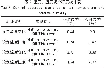
Figure 6 shows the scatter plots of set temperature, humidity and measured temperature and humidity at 96 measurement points within the next day of the set temperature and humidity changes. Fig. 6(a) and Fig. 6(b) are scatter plots of the set value and measured value of the relative humidity set value change and the constant condition, respectively. Fig. 6(c) and Fig. 6(d) are the temperature setting. Scatterplots of setpoint and measured values ​​for constant value changes and constant conditions.
Figure 6 Comparison of temperature and humidity control accuracy 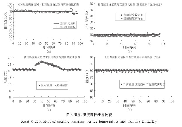
Through experimental data analysis, regardless of the temperature or temperature, the temperature control has a higher accuracy, and is 50% higher than the design specifications. For humidity control, the simulated low humidity environment is more difficult than the simulated high humidity environment, and the low humidity is not as high as the high humidity in the control accuracy. However, in that case, it is still within the design technical scope. .
The regulation precision of the light factor can be explained from two aspects: one is the composition of the light wave, and the other is the size of the photo-quantum flux density irradiated on the plant body. The former has met the requirements of light wavelength for photosynthesis of plants through the combination of light sources of sodium lamps and metal halide lamps. The latter was measured using a Li-6400 plant photosynthesis instrument. The photon flux densities of three groups of light sources designed and installed were 180 to 300 μmol/m2·s, 300 to 800 μmol/m2·s, and 800 to 1150 μmol/m2·s, respectively. Meet the technical specifications of the design requirements.
It should be noted that the measured photon flux density has a significant positive correlation with the distance from the measurement section to the light source. That is, under the same set of light conditions, the closer the plant is to the light source, the higher the photon flux density value. In the actual experiment process, the spatial position and light source combination of the climate chamber are reasonably used, and the designed lighting parameters can be obtained by means of actual measurement and calibration of the photosynthesis instrument.
The regulation of CO2 is relatively simple. When the concentration of CO2 in the climate chamber is lower than the atmospheric background, the CO2 control system starts to work, opening the nozzle of the CO2 cylinder and controlling the solenoid valve. If the CO2 concentration in the climate chamber is higher than the atmospheric background value, the ventilation system can quickly reduce to the set value.
5 Conclusions (1) This climate chamber aims at simulating the arid climate environment. The selection of technical indicators, the design of technical solutions and their construction have met the characteristics and requirements of the simulated arid climate environment. Achieve: (1) temperature, humidity and CO2 and other parameters of the program control, to meet the requirements of a constant or gradual (2) configuration in line with the growth and development of light sources, the light source spectrum and solar spectral lines similar (; 3) configuration Fresh air and exhaust system, air distribution, heating and cooling methods are reasonable, energy-saving effect is good; (4) has a network of hierarchical management and remote management capabilities, and has a mobile phone wireless signal supply equipment alarm function abnormal operation.
(2) The application of modern advanced technologies to the development of artificial climate chambers has greatly improved the technological level of artificial climate chambers, such as automatic control theory and technology, computer network and communication technology, and sensor technology. This means that the comprehensive application of cross-disciplinary and advanced science and technology is an important way to improve the science and technology level of scientific research experimental platforms.
Equipment model
Rice output(kg/h)
Milled rice rate(%)
Weight of equipment(kg)
Equipment power(kw)
Dimension(L×W×H)
Power input(V/Hz)
MLNS 20/15
700-1000
69-75
1650
33
3200×1900×3000
380/50

Artificial arid climate climate chamber design and function