Centrifugal submerged pump maintenance and repair methods

1 General
1.1 The scope of application
This procedure applies to FY submerged pump , FYW submerged pump, FSY submerged pump, HYF submerged pump, YW submerged pump maintenance and overhaul, other centrifugal submerged pump can be used as a reference.
1.2 Structure Description
Anti-corrosion liquid under the pump for the single-stage single-suction centrifugal pump under the type of its components to the pump body, pump cover, floor, pump section, pump shaft, impeller, bushings, couplings, bearings, bearings and other zero Components.

Table 1
Flow rate m 2 / n
Head m
Number of revolutions r / min
Power kW
3.6 ~ 360
12 ~ 49
2900 ~ 1450
1.5 ~ 7.5
1.3 equipment performance
Equipment performance in Table 1.
2 good standard
2.1 zero, parts
2.1.1 Zero, complete components, quality meets the requirements.
2.1.2 The foundation, the base is firm and complete, the quality meets the requirements.
2.1.3 pipelines, valves , brackets, installation is reasonable, clear signs,
2.1.4 Corrosion meets the requirements.
2.2 operating performance
2.2.1 smooth operation of the device without noise, the current does not exceed the rated value.
2.2.2 pressure, steady flow, the Ministry of normal temperature.
2.2.3 conscientiously implement the "five", "three filter" lubrication management system.
2.2.4 equipment capacity to meet the nameplate requirements or to meet production needs.
2.3 technical information
2.3.1 Technical file is complete, the data is accurate and reliable.
2.3.2 random certificate, product manual is complete.
2.3.3 equipment assembly drawings and consumables complete.
2.3.4 running record is complete.
2.3.5 maintenance and inspection records are complete.
2.3.6 maintenance inspection procedures, complete operating procedures.
2.4 Equipment and Environment
2.4.1 Equipment clean, no dust, grease and debris on the surface and around.
2.4.2 equipment and ancillary pipeline no running, run, drip, leak.
3 equipment maintenance
3.1 routine maintenance
3.1.1 Check the equipment for any abnormal vibration or sound.
3.1.2 Check the pressure, flow and temperature of each department is normal, and make a record.
3.1.3 conscientiously implement the "five", "three filter" lubrication management system.
3.1.4 regular inspection packing seal, packing leakage over the provisions of timely replacement.
3.1.5 often check the various departments bolts loose phenomenon or vibration caused by loosening.
3.1.6 Check the shaft sleeve cooling pipe is smooth.
3.1.7 Check the Department of sealing point run, run, drip, leak phenomenon.
3.1.8 each class do a good job of cleaning equipment.
3.2 regular inspection of the content
3.2.1 Injected oil into the bearing once a month, three months to clean the oil change.
3.2.2 The pump once a month to conduct a comprehensive inspection run.
3.3 common troubleshooting methods
Common troubleshooting methods in Table 2
Table 2
3.4 Emergency Parking
Stop in case of one of the following conditions:
a. When the submerged pump has abnormal noise;
b. When the liquid level in the tank is lower than that of the submerged pump working impeller;
c. When the motor current exceeds the rated value does not drop.
4 inspection cycle and maintenance content
4.1 maintenance cycle
Maintenance cycle in Table 3.
When the pump power is less than 20kW no overhaul, change the repair content for overhaul

table 3
Maintenance category
Minor repair
In the repair
Maintenance cycle, month
3
6 ~ 12
4.2 maintenance content
4.2.1 minor repair
4.2.1.1 Check all the bolts fastening.
4.2.1.2 inspection replacement filler.
4.2.1.3 Check the cooling water pipe.
4.2.1.4 Change the lubricant (grease).
4.2.1.5 find a positive coupling, wearing parts replacement.
4.2.2 (large) repair
4.2.2.1 include minor repairs.
4.2.2.2 disintegration inspection of each zero, wear parts, corrosion, to be repaired or replaced.
4.2.2.3 Determination of static balance impeller and the amount of rotor sloshing.
4.2.2.4 Check the bearing wear, replace if necessary.
4.2.2.5 Check and adjust impeller seal ring, bushings, bushings and other parts of the gap, wear serious replacement.
4.2.2.6 rust corrosion.
5 maintenance methods and quality standards
5.1 pump housing and pump cover
Pump housing and pump cover should not have cracks, trachoma, slag and other defects. Wall thickness and precision machining department should meet the requirements.
5.2 floor (pump seat)
5.2.1 The bottom plate should be no cracks, the surface smooth and flat.
5.2.2 pump body, bearing seat, pump cover and sleeve assembly to maintain the coaxiality Φ0.05mm. Range.
5.3 pump section
Pump end face should be perpendicular to the tube center line; coaxial with the tube center, coaxiality Φ0.05mm.
5.4 pump shaft
5.4.1 pump shaft should not have cracks, corrosion and other defects.
5.4.2 pump shaft material and the deviation of the size of the ministries should be consistent with the pattern, journal roundness and cylindricity of 0.04mm.
5.4.3 Install the shaft at the impeller and the assembly coupling with a surface roughness of 3.2; assemble the journal at the rolling bearing with a surface roughness of 1.6.
5.4.4 pump shaft straightness 0.05mm / m.
5.4.5 When assembling the upper and lower shaft, the axial channeling amount is not more than 1.5mm.
5.4.6 Keyway centerline offset of the journal centerline is not greater than 0.06mm, skew tolerance of not more than 0.03mm.
5.4.7 key and keyway side should be closely matched; not allowed to add gaskets. When the keyway wear, wear can be appropriately increased. Increase can only increase by a standard size. The keyway can be opened in the 90º or 120º direction of the keyway as the structure and the force allow.
5.4.8 After the journal wear, plating or spraying method can be used to repair.
5.5 sleeve
5.5.1 sleeve surface should not have trachoma, porosity, porosity and other defects.
5.5.2 sleeve inner and outer surface should be processed. Hub and shaft or bushing contact surface roughness of 1.6; and filler in contact with the external surface roughness of 1.6.
5.5.3 Sleeve and bushing clearance Table 4 provides:
5.6 impeller
5.6.1 impeller surface and liquid flow channel wall should be clean, no cracks, sticky sand, burrs and other defects.
5.6.2 Impeller shaft hole and axis with the general use of H7 / h6.

Table 5 mm
Impeller outer diameter
≤50
> 50 ~ 120
> 120 ~ 260
Radial runout tolerance
0.05
0.06
0.07
5.6.3 Radial diameter of the impeller radial runout tolerance according to Table 5:
Table 4 mm
medium
Alkali
acid
gap
0.40 ~ 0.45
0.60 ~ 0.65

5.6.4 Before the new impeller should be static balance, static balance tolerance according to Table 6 regulations. Exceeding the values ​​in the table, use the double-weight method to cut the cover plates on both sides of the impeller. The cutting thickness should not exceed 1/3 of the wall thickness. The cutting position and the last cutting position should be smoothly connected.

Table 6
Impeller diameter, mm
<200
201 ~ 300
301 ~ 400
401 ~ 500
Allow uneven weight, g
2
4
6
8
5.7 Rolling bearings
5.7.1 roller bearing roller and raceway, inside
The outer surface should be no scars, pitting, corrosion and other deficiencies
trap. Cage intact, smooth contact, rotation
No noise.
5.7.2 When assembling bearings, the bearings must be cleaned with a cleaning agent to remove dirt and other residual substances, then coated with grease. Such as the use of heating method should be 100-120 ℃ in the machine pool oil bath bearing assembly after 10-15 minutes. It is forbidden to heat the flame directly when assembling.
5.7.3 removable bearings should be used special tools or presses, not directly hit the bearing with a hammer.
5.8 Couplings
5.8.1 coupling with the shaft, the general use of H7 / J6 or H7 / K6.
5.8.2 Flexible sleeve pin coupling shaft deviation and the gap between the two ends should be in accordance with the provisions of Table 7.

Table 8 mm
Coupling
Outer diameter
Face
gap
Deviation in the middle
Radial displacement
Tilt axially
90 ~ 160
195 ~ 220
280 ~ 320
360 ~ 400
2.5
3
4
5
<0.05
<0.05
<0.08
<0.08
<0.2 / 1000
5.8.3 elastic pin coupling shaft centering deviation and the gap should be consistent with the provisions of Table 8.
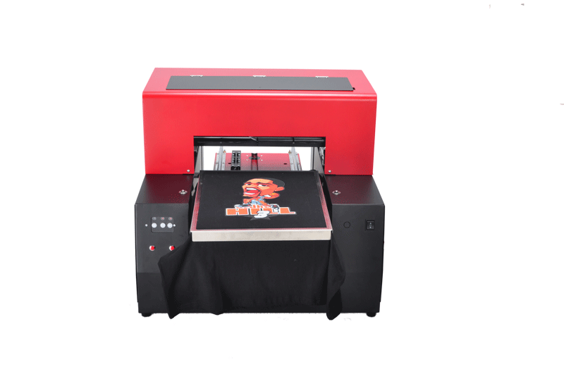
Table 7 mm
Coupling
Outer diameter
Face
gap
Deviation in the middle
Radial displacement
Tilt axially
70 ~ 106
130 ~ 190
224 ~ 250
310 ~ 400
3
4
5
5
<0.04
<0.05
<0.05
<0.08
<0.2 / 1000

5.9 packing seal
5.9.1 packing seal gland and shaft or sleeve radial clearance of 0.75-1.00mm, remained evenly around.
5.9.2 packing seal Gland and packing box depth of a circle packing height, but the minimum shall not be less than 5mm. Gland shall not be askew, elastic appropriate.
6 test and acceptance
6.1 test preparation before
6.1.1 clear all around the pump seat and debris.
6.1.2 Check all the connecting bolts are tightened.
6.1.3 Check the tightness of packing and gland packing is skewed.
6.1.4 Check the bearing grease enough; cooling system is smooth.
6.1.5 crank two weeks, pay attention to whether there is no noise in the pump, crank light is.
6.1.6 Check the motor rotation is correct.
6.1.7 Install the coupler pin and prepare it for test.
6.2 test
6.2.1 Open the valve to the tank pipe to fill the tank with liquid and close the pump outlet pipe valve.
6.2.2 start the motor with the jogging method, check the operation without exception before continuing to test.
6.2.3 When the pump reaches the normal speed, gradually open the pump pipe valve.
6.2.4 load test 2 hours.
6.2.5 load test should meet the following requirements:
a. Smooth operation without noise;
b. flow, pressure steady;
c. current stability, does not exceed the rated current;
d. Bearing temperature does not exceed 75 ℃ ;.
e. ministries no running point, run, drip, leak;
f. Achieve nameplate output or identify capacity.
6.3 Acceptance
6.3.1 Inspection quality to meet the standards of this procedure.
6.3.2 test pass.
6.3.3 maintenance record is complete.
6.3.4 Handover procedures.
7 Maintenance Inspection safety precautions
7.1 Maintenance Safety Precautions
7.1.1 must strictly implement the process rules and the safety system.
7.1.2 can not be reversed operation.
7.1.3 can not run the fluid.
7.1.4 submerged pump with cooling water shall not be interrupted operation.
7.1.5 running leaks and loose phenomenon, to stop handling.
7.2 maintenance safety precautions
7.2.1 Submerged pump maintenance, must be approved for the maintenance of equipment spending procedures.
7.2.2 equipment maintenance, you must cut off the power, hang up "forbidden card" sign before maintenance.
7.2.3 All firefighting operations at the production site must be handled "moving fire permit."
7.2.4 maintenance tools, demolition, cleaning of parts and components, neat and tidy, civilized construction.
7.2.5 into the pit, overhaul maintenance, to carry out analysis of harmful gases and oxygen content, so as not to poison.
7.3 test safety precautions
7.3.1 Commissioning work, there must be someone to command.
7.3.2 Clearly set test signs, prohibit unrelated personnel to enter the test site.
7.3.3 After the test run, the operator closes the valve and stops operating according to the stopping procedure and informs the electrical department of the power failure.
Table 1
Flow rate m 2 / n
Head m
Number of revolutions r / min
Power kW
3.6 ~ 360
12 ~ 49
2900 ~ 1450
1.5 ~ 7.5
Flow rate m 2 / n
Head m
Number of revolutions r / min
Power kW
3.6 ~ 360
12 ~ 49
2900 ~ 1450
1.5 ~ 7.5
table 3
Maintenance category
Minor repair
In the repair
Maintenance cycle, month
3
6 ~ 12
Maintenance category
Minor repair
In the repair
Maintenance cycle, month
3
6 ~ 12
Table 5 mm
Impeller outer diameter
≤50
> 50 ~ 120
> 120 ~ 260
Radial runout tolerance
0.05
0.06
0.07
Impeller outer diameter
≤50
> 50 ~ 120
> 120 ~ 260
Radial runout tolerance
0.05
0.06
0.07
medium
Alkali
acid
gap
0.40 ~ 0.45
0.60 ~ 0.65
Table 6
Impeller diameter, mm
<200
201 ~ 300
301 ~ 400
401 ~ 500
Allow uneven weight, g
2
4
6
8
Impeller diameter, mm
<200
201 ~ 300
301 ~ 400
401 ~ 500
Allow uneven weight, g
2
4
6
8
Table 8 mm
Coupling
Outer diameter
Face
gap
Deviation in the middle
Radial displacement
Tilt axially
90 ~ 160
195 ~ 220
280 ~ 320
360 ~ 400
2.5
3
4
5
<0.05
<0.05
<0.08
<0.08
<0.2 / 1000
Coupling
Outer diameter
Face
gap
Deviation in the middle
Radial displacement
Tilt axially
90 ~ 160
195 ~ 220
280 ~ 320
360 ~ 400
2.5
3
4
5
<0.05
<0.05
<0.08
<0.08
<0.2 / 1000
Coupling
Outer diameter
Face
gap
Deviation in the middle
Radial displacement
Tilt axially
70 ~ 106
130 ~ 190
224 ~ 250
310 ~ 400
3
4
5
5
<0.04
<0.05
<0.05
<0.08
<0.2 / 1000

T Shirt Printer

We are manufacture in Shenzhen China.


Do you want to own a unique T-shirt?

Do you want to DIY a T-shirt special for your kids, your lover and your family?

Do you want to open a workshop for the T-shirt printing business?

Imagination is unlimited; Gateway can give you a complete solution for customizing your t-shirts.

T shirt printer are using 5 color eco environmental ink (C,M,Y,K,W). Printing size is 33*60cm,max printing height is 17cm,max resolution is 5760*1440dpi.With our T-shirt printer, you can print any kind of artwork or photos on your own T-shirts, no mater White or Black shirts.

The operation is very simple; You just put the T-shirt on our t shirt jig/adapter.


t shirt printer

Name
T shirt printer
Print head
DX5
Printer size
33*43cm(33*60cm)
Printing speed
A4 photo/111s
Printng resolution
5760*1440dpi
Nozzles
90*6=540
Interface
USB2.0
Net weight/Gross weight
55Kg/60Kg
Printer size
750*630*510mm
Height adjustment
Automatic
Working power
110V/220V 50/60Hz 30-75W
Operation system
Windows 7/XP/2000/Vista etc
Temperature
5-35o


T Shirt Printer,Digital T Shirt Printer,T Shirt Printing Machine,Black T Shirt Printer,A3 T Shirt Printer

Shenzhen Refinecolor Technology Co., LTD. , https://www.sztshirtprinter.com